Sunday 17 July 2022

Types Of Network Analysis

Types Of Network Analysis in ArcGIS

 What is Network Analysis in ArcGIS ?

ArcGIS Network analysis provides network-based spatial analysis tools for solving complex routing problems. It uses a configurable transportation network data model allowing organizations to accurately represent their unique network requirements.

Types of Network Analysis

1) Route
2) Service areas
3) Closest facility
4) OD cost matrix
5) Vehicle routing problem
6) Location allocation
7) Time dependent analysis

Route:

        Route organization Analyst can track down the most ideal approach to get starting with one area then onto the next or to visit a few areas. The areas can be indicated intelligently by putting focuses on the screen, entering a location, or utilizing focuses in a current component class or highlight layer. In the event that you have multiple stops to visit, all that course can be resolved for the request for areas as determined by the client. Then again, Network Analyst can decide the best succession to visit the areas, which is known as taking care of the mobile sales rep issue.

What is the best route?

        Regardless of whether tracking down a basic course between two areas or one that visits a few areas, individuals normally attempt to take the best course. In any case, "best course" can mean various things in various circumstances. 

        All that course can be the speediest, briefest, or most panoramic detour, contingent upon the impedance picked. Assuming the impedance is time, the best course is the speediest course. Consequently, all that course can be characterized as the course that has the least impedance, where the impedance is picked by the client. Any legitimate organization cost trait can be utilized as the impedance while deciding the best course. 

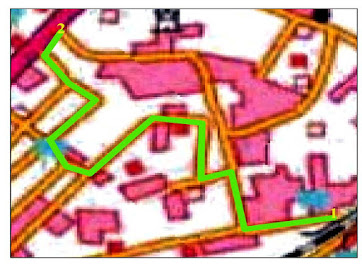
        In the model beneath, the main case utilizes time as an impedance. The fastest way is appeared in blue and has an all out length of 4.5 miles, which requires 8 minutes to navigate.


In the following case, distance is picked as the impedance. Subsequently, the length of the briefest way is 4.4 miles, which requires 9 minutes to cross. 

Alongside the best course, Network Analyst furnishes headings with turn-by-turn maps that can be printed. 

Service areas:

        With Network Analyst, you can discover administration regions around any area on an organization. An organization administration region is a locale that envelops every single available road, that is, roads that exist in a predefined impedance. For example, the 10-minute help region for an office incorporates every one of the roads that can be reached inside a little ways from that office.

Closest facility:

        Tracking down the nearest emergency clinic to a mishap, the nearest squad cars to a crime location, and the nearest store to a client's location are altogether instances of nearest office issues. When discovering nearest offices, you can indicate the number of to discover and whether the course of movement is toward or away from them. Whenever you've tracked down the nearest offices, you can show the best course to or from them, return the movement cost for each course, and show bearings to every office. Also, you can indicate an impedance cutoff past which Network Analyst ought not look for an office. For example, you can set up a nearest office issue to look for emergency clinics inside 15 minutes' drive season of the site of a mishap. Any clinics that take longer than 15 minutes to arrive won't be remembered for the outcomes.


The medical clinics are alluded to as offices, and the mishap is alluded to as an episode. Organization Analyst permits you to play out numerous nearest office examinations all the while. This implies you can have different episodes and track down the nearest office or offices to every occurrence.

OD cost matrix:

        With Network Analyst, you can make a beginning objective (OD) cost lattice from different starting points to numerous objections. An OD cost lattice is a table that contains the organization impedance from every beginning to every objective. Furthermore, it positions the objections that every beginning interfaces with in rising request dependent on the base organization impedance needed to make a trip from that beginning to every objective.

        The best organization way is found for every beginning objective pair, and the expense is put away in the trait table of the yield lines. Despite the fact that the lines are straight for execution reasons, they generally store the organization cost, not straight-line distance. The realistic underneath shows the consequences of an OD cost framework examination that was set to discover the expense to arrive at the four nearest objections from every beginning.


The straight lines can be represented differently, for example, by shading, addressing which point they begin from, or by thickness, addressing the movement season of every way.

The straight lines can be represented differently, for example, by shading, addressing which point they begin from, or by thickness, addressing the movement season of every way.

Vehicle routing problem

        A dispatcher dealing with an armada of vehicles is frequently needed to settle on choices about vehicle directing. One such choice includes how to best allot a gathering of clients to an armada of vehicles and to arrangement and timetable their visits. The targets in taking care of such vehicle directing issues (VRP) are to give a significant degree of client support by regarding any time windows while keeping the generally speaking working and speculation costs for each course as low as could really be expected. The requirements are to finished the courses with accessible assets and inside as far as possible forced by driver work shifts, driving paces, and client responsibilities.

     Organization Analyst gives a vehicle steering issue solver that can be utilized to decide answers for such complex armada the executives errands.

        Consider an illustration of conveying products to supermarkets from a focal distribution center area. An armada of three trucks is accessible at the distribution center. The stockroom works just inside a specific time window-from 8:00 a.m. to 5:00 p.m.- during which all trucks should return back to the distribution center. Each truck has a limit of 15,000 pounds, which restricts the measure of merchandise it can convey. Each store has an interest for a particular measure of merchandise (in pounds) that should be conveyed, and each store has time windows that limit when conveyances ought to be made. Moreover, the driver can work just eight hours of the day, requires a break for lunch, and is paid for the sum spent on driving and overhauling the stores. The objective is to thought of an agenda for every driver (or course) with the end goal that the conveyances can be made while respecting all the assistance prerequisites and limiting the all out time spent on a specific course by the driver. The figure beneath shows three courses got by tackling the above vehicle steering issue. 

Location - allocation

Area allotment assists you with picking which offices from a bunch of offices to work dependent on their expected collaboration with request focuses. It can help you answer addresses like the accompanying:

            1) Given a bunch of existing fire stations, which site for another fire station would give the best reaction times to the local area?

               2) On the off chance that a retail organization needs to cut back, which stores would it be advisable for it to near keep up the most in general interest?

                3) Where should a processing plant be worked to limit the distance to circulation focuses?

In these models, offices would address the fire stations, retail locations, and production lines; request focuses would address structures, clients, and dispersion focuses.

The goal might be to limit the general distance between request focuses and offices, amplify the quantity of interest focuses covered inside a specific distance of offices, augment an allocated measure of interest that rots with expanding distance from an office, or boost the measure of interest caught in a climate of cordial and contending offices. 

The guide underneath shows the consequences of an area designation examination intended to figure out which fire stations are repetitive. The accompanying data was given to the solver: a variety of fire stations (offices), road midpoints (request focuses), and a greatest suitable reaction time. The reaction time is the time it takes firemen to arrive at a given area. The area designation solver discovered that the local group of fire-fighters can close a few fire stations and still keep a three-minute reaction time. 

A guide of 16 fire stations: the seven that are needed to stay open to cover request focuses inside three minutes, and the nine that could close.

Out of the current arrangement of fire stations, nine fire stations can close, and at least seven are required for the office to in any case have the option to react to crises inside three minutes. 

Time dependent analysis

        The entirety of the solvers recorded above permit you to consolidate live and verifiable traffic information into an investigation so you can track down the best course for a given time frame of day; find the best spot to relational word an emergency vehicle at 8:00 a.m., 12:00 p.m., 4:00 p.m, etc; and create administration regions for various times. The aftereffects of any examination may change for various dates and times since traffic conditions and travel times may change.

Thursday 23 September 2021

Network Dataset Layer

How to Network Dataset Layer        

A Network analysis layer can not be created without a link to a network dataset, by adding a network dataset layer to ArcMap you are also providing a link to the dataset and can subsequently create analysis layer using the Network Analyst toolbar.

Adding a Network Layer

Add a Network Layer to ArcMap follow the steps:

1) Open ArcMap
2) Click the Catalog Window button on the standard toolbar. The catalog window opens.
3) using the catalog window navigate to the location of the Network dataset and drag it into table of contents. The adding Network Layer dialog box open.
4) Click no to only add the Network dataset to map optionally click yes to add the Network dataset and all it is source feature classes to the map.
The Network dataset is added to ArcMap as a Network layer.

The following list point out which elements a Network layer renders by default when add to ArcMap initially:

  • if the network dataset does not have traffic data only edges are displayed.
  • if the network dataset has traffic data only traffic is is displayed.
  • if time is not enabled traffic for the current time and day is shown.
  • if time is enabled traffic for the time specified on the time slider is shown.

        Network element can be queried with the network identify tool on the network analyst toolbar and the identify tool on the tools toolbar. However they cannot be select interactively in ArcMap. Moreover select by attributes, select by location and select by graphics cannot be used to create selection sets on a network layer.

Network Layer Symbology

The symbology of network element can be modified on the network layers Layer Properties dialog box on the Symbology tab.


You can open the Layer Properties dialog box by double - clicking the name of the layer in the Table Of Contents window.


Showing and Hiding Network Elements  

You can show or hide certain types of network element on the map by checking or unchecking them in the show list. When a network dataset supports traffic data, only Traffic is checked by default, otherwise only Edges is checked by default.

What are dirty areas ?

Dirty areas allow you to see where edits to source features have been made since the last time the network dataset was built. Rectangles surround and highlight  the portions of the network dataset that are out of data due to the edits.

When you rebuild the network only the dirty areas are rebuilt, which can be much faster than rebuilding the entire network.

The next peri of graphics demonstrates a scenario in which dirty areas are generated:


if properties of the network dataset are altered the entire network dataset may be covered by a dirty area indicating all the elements of the network need to be rebuilt.


Changing the symbology of edges, junctions, system junctions, turns and dirty areas

you may need to modify the default symbology of items contained within a network dataset layer, the follow steps show how to change the symbology for edges, system junctions. turns and dirty areas ''Changing the symbology for traffic is described later''

1) open the layer properties bialog box by double clicking the network dataset layer in the  arcmap table of contents.

2)  Click the symbology tab.

3) in the show list, click the name of the element that you want to symbolize differently, the element name is selected.

4) in the symbol section to the right click the large button, which show an example of the current symbol on it.

5) use the symbol selector dialog box that opens to define a new symbol for the element.

6) click ok, the symbol selector dialog box closes.

7) click ok, the layer properties dialog box closes.


Displaying traffic

Instructions and tips for displaying traffic are covered in the visualizing traffic topic.

Symbolizing restrictions with arrows

Arrows in a network layer are symbols that can be displayed on edges and traffic elements to mark restrictions. Although any kind of restriction can be symbolized with arrows, it is advised that you only use this dialog box to display prohibit restrictions such as one way street bidirectional streets and streets that prohibit traversal in both directions. To display or prefer- restrictions such as designated road for hazmat you should symbolize your source features accordingly.

The steps below describe how to display arrows:

1) Open the layer properties dialog box by double click the network dataset layer in ArcMap table contents.

2) Click the symbology tab of the layer properties dialog box.

3) In the show list click either edges or traffic to select it.

4) In the symbol section to the right – click arrows, if you are add arrows to traffic click advanced>arrows. The arrows dialog box opens.

5) Check draw arrows on edges.

6) Choose whether you want symbols placed in the middle or at the end of edges

7) From the restriction attribute drop – down list choose the restriction you want to symbolize. 

8) Choose which restrictions cause a symbol to be draw on network edges.

9) Click ok. The arrows dialog box closes.

10) Click ok. The layer properties dialog box closes.

Applying source filters

Source filters allow you to choose a subset of network elements to draw on the map. A previous section demonstrated how to show or hide network elements on the source feature classes they are derived from. You can further limit the drawing of network elements by writing an SQL expression. Only the features that meet the criteria specified in the expression are drawn.

Following steps how to create a source filter:

1) Open the layer properties dialog box by double click the network dataset layer in the ArcMap table of contents.

2) Click the symbology tab of the layer properties dialog box.

3) In the show list click the name of one of the following item; edges, traffic, junctions, system junctions or turns.

4) In the source filters section to the right click the source filters button. If you are adding a source filter to traffic click advanced>source filters. The source filters dialog box opens.

5) In the show sources list check the source feature classes that you want to see in the map display. You can further limit which elements from the source classes are drawn in the map by creating a query expression.

6) Click the name of a source feature class in the show sources list and enter an SQL query using the source query expression pane.

Only features that meet the criteria specified by the query are displayed in the map.

You can repeat this step for any other source feature class in the show sources list.

7) Click ok. The source filters dialog box closes.

8) Click ok. The layer properties dialog box closes.

Other network layer display settings

The network layer supports scale ranges, which specify the scales at which the network layer is visible. These can be set on the general tab of the layer properties dialog box.

The display tab allows you to configure symbols to scale when a reference scale is set. Additionally you can set transparency and map tips for the network layer there. Map tips for a network layer can be used to display either the element ID of network element or the value of any network attribute.

Saturday 22 May 2021

How to Creating a map layout in ArcGIS

             A layout is a collection of map elements laid out and organized on a page. Common map elements include one or more data frames each containing an ordered set of map layer, a scalebar, north arrow. map title, descriptive text, and a legend. Layout view is where you add map surrounds, frames, graticules, and other finishing touches to a map. What you see on the layout is what you get if you print or export the map to the same page size.


creating a Map Layout

 Below are the general steps for laying out a map in ArcMap:- 

 1. Create, edit, and symbolize your data symbolize your data as appropriate.

 2. In layout view, click the insert menu to add elements onto your layout. If you have  more than one data frame in your map, the elements you insert will relate to the active data frame. For example when you add a scale bar to the map, it will reflect the scale of the active data frame and update if you change the scale of that data frame. Once you've added an element to your map, you can right click it and click properties to set additional options.

 3. Add other text or graphics, such as metadata notes, borders, and frames, using the Draw toolbar. You can use guides, grids, and rulers to help you precisely position elements on your page. The commands on the graphics toolbar or the drawing menu of the draw toolbar can help align, group and order the elements on the page. In addition, you can use the data frame properties dialog box to create other effect, such as inset maps, clip the shapes of data frames.


 4. Edit and finish your map elements to complete your map. As a last step, you may need to convert some of your map elements to graphics so you can have complete control over their appearance and make manual edits to the elements. However, as a graphic, the element loses its connection to the data frame. For example, if you convert a a legend to a graphic then later add a layer to your map, the legend as a graphic will not reflect this update.

 5. Print and publish your map. you can also save your layout, including the data in the map, as a template, and use it as a starting point for further mapping and analysis. Map templates make it easy to produce maps that conform to a standard and they save time by letting you do the layout work for all the maps in the series at once.

Data Frames

perhaps the most important part of a map is the geographic data. Geographic data is presented in the layout in a data frame. Simple maps usually have a single data frame, but some maps have multiple data frames.

The shape and orientation of the geographic feature you're depicting may influence the size and shape of the data frame on the map as well as the orientation of the map on page.

Aesthetic criteria, limitations of the media that you use to reproduce the map and the number and size of other elements that you add to the will affect your choice of page size and orientation. 

Having more than one data frame in a map

You can add as many data frames to your map as you need and arrange them in the page layout. When you have more than one data frame in a map, you need to be aware of which data frame is active. Many of the ArcMap tools and commands work on the active data frame.

you can tell which data frame is active by confirming that its name is shown in bold in the table of contents. In addition, when a map contains more than one data frame, the active data frame is shown with a light dotted line around its border. The diagram below shown the various states of a data frame in layout view. 

   
Top Left - Inactive data frame
Top Right - Active data frame
Bottom Right - Focused data frame.
Bottom Left - Active data frame selected with the select elements tool. You can move around on the layout, resize it delete it and so on.

        If you have many data frames in a layout, you may find that map composition tasks are slowed down by having to draw each data frame as it moves. you can set a data frame to use draft mode drawing, which means it only draws the border and the data frame's name in the middle of its extent in layout view. There is also a toggle draft mode button on the Layout toolbar that will toggle whether all data frame are shown in draft mode. 

How to add data frames 

Add a new data frame to a map;

 1. Click the insert menu and click Data Frame.
     You can add any data to the new data frame.


Making a data frame active;

1. Click the select elements tool.
2. Click the data frame in layout view.

Copying a data frame;

1. Click the data frame in layout view to select it.
2. Click the edit menu and click copy.
3. Click the edit menu and click paste. 
4. Click the copy, Located on top of the original data frame, and drag it to a new place on the page.

Resizing a data frame;

1. Click the data frame to select it.
2. Click a selection handle and drag it to change the size of the data frame.

Printing and exporting from ArcMap 

There are numerous options for map printing and exporting in ArcGIS. A map can be printed directly to a printer or it can be exported to a graphics file such as PDF and JPEG. You can export from data view or layout view in ArcMap. From layout view, the page layout will be output, from data view, the visible extent of the data frame will be output.

The ArcMap printing functionality includes the windows printer engine for typical map prints, as well as the ArcPress printer engine for printing large or complex maps to a large format printer.

The ArcMap map export functionality allows you to export a map to any of TEN formats. These include five raster formats: BMP, JPEG, PNG, TIFF, GIF and five vector formats: EMF, PDF, EPS, SVG and Adode illustrator.

How to print a map

Previewing a map;
1. Click the file menu and click print preview.
2. Examine the preview.
3. Click print if you want to continue and print, otherwise, click close.

Choosing a printer engine;

1. Click the menu and click print.
2. Click the printer engine drop-down arrow and choose a printer engine.
3. Click Ok.

Printing a map;

1. Click the file menu and click print.
2. Verify the printer engine is set properly. If it is not, change it, then click properties and verify the settings for the printer driver.
3. Verify the output image quality is set properly.
4. If the map page size is larger than the printer paper size, then the Tile map to printer paper option will be enabled and selected. If you do not want to tile your      print, click Scale Map to fit Printer Paper. To proceed regardless of possible clipping, click tile map to printer paper and choose to print tiles 1 to 1.
5. Click the Number of Copies arrows to increase or decrease the number of printed maps. Optionally, check print to file. You will be prompted for a file name after you click Ok.
6. Click Ok.


How to Creating a map layout in ArcGIS


Sunday 11 April 2021

How To Creating Geodatabase and Feature Class in ArcGIS

Introduction

                          Now you are going to begin digitizing features of this image. Digitzing is the process of making features we can see on the toposheet (name of image or toposheet) image editable and making them features to which additional spatial and non - spatial attributes can be assigned. This means we are going to follow a process of making digital versions of objects that will have an attribute table associated with them. our primary goal will be digitizing the wards, which are objects that occupy an area on the map, once they are digitized and have an associated attribute table these objects will also be  known as polygons features. in an accompanying document  you have data on the home country of mother by ward. when digitizing we can digitize point, line, and polygon. by digitizing these features you make them available for mapping once you have added the tabular data to the attribute table "as you know there are a few ways can do this" the digitizing process is started by creating new layers in ArcCatalog and then adding features to them in ArcMap.

What is Digitization in GIS ?

Digitization in GIS is the process of converting geographic data a scanned image into vector data by tracing the features. Digiting process, features from the image are captured as coordinates in point, line, and polygon formatting.

Summary

ArcGIS can digitize or trace features without mouse or puck click using several.
options: streaming, tracing or freehand drawing. with these methods, the mouse pointer is trace the desired feature.

Procedure

There are three options provided to do this:-
Digitize by streaming, Digitize by tracing, and Digitize by freehand drawing.

Digitize by tracing

Tracing is used to create a new feature which follow the shape of an existing feature. Tracing can be done by tracing directly over an existing feature or at an offset value.

1. Start an edit session.

2. Navigate to editor toolbar, and click the Create Features button. This opens the Create Features window.

3. Select the layer to edit and the Construction tools.

4. Navigate to the editor toolbar, and click the trace tool.

5. Click the map, and start tracing by moving the pointer.


6. To close the tracing session, right-click > Finish Sketch.

7. To complete one part of digitizing a feature, right-click > Finish Part. click the map again to start digitizing another feature.

Digitize by freehand drawing

Freehand drawing is used to create lines according to the movement of the pointer. The segments created are smooth and features or boundaries on the map. This option is suitable for drawing quick, free-forming lines on the map.

1. Start an edit session.

2. Navigate to the editor toolbar, and click the Create Features button. This open the Create Features window.

3. Select the layer to edit.

4. For Construction tools, select Freehand.


5. Click the map, and start the freehand drawing by moving the pointer.

6. Click the map once to stop the drawing session.

Creating Geodatabase and Feature Class

Step-1 Click Add Data and add the given toposheet (TIF File).


Step-2 Open Arc Catalog.


Step-3 Click on the destination folder where to create the Geodatabase.


Step-4 Right click on the folder.


Step-5 Click ‘New’ and another dialogue box appears.


Step-6 Click on either ‘File Geodatabase’ or ‘Personal Geodatabase’ to create a new Geodatabase.


Step-7 A new Geodatabase will be created and rename the Geodatabase according to our wish.

Here, ‘toposheet geo.tif’ is the given name for the created Geodatabase where.gdb is the extension of the Geodatabase.

Right click on the created ‘toposheet.geo’ and new dialogue box will appear.

Step-8 Click on the ‘Feature class’ to create new feature classes.

A new dialogue box will appear in which name of the new feature class and the type of    feature such as point, line polygon is given and new feature classes are created.

Step-9 Here, point feature is created.

After entering the name and type click next.

Step-10 On clicking next, co-ordinates are selected for the feature class.


Here, WGS1984  UTM  Zone 43N is selected according to the selected Toposheet. Note-(study area Change the coordinating system to suit you will be selected))


Step-11 Click next.

Step-12 Click next.


New feature class is created.


Likewise the point and polygon feature classes are created.


The selected grid shown in the image is used for further digitization by creating point, line and polygon shape files.

Step-13 Digitize the point features (home).


Step-14 Digitize the line features (road).


Step-15 Digitize the polygon features (field).


 *Finalize the map.


                                          ArcMap Digitization Practice Video...